


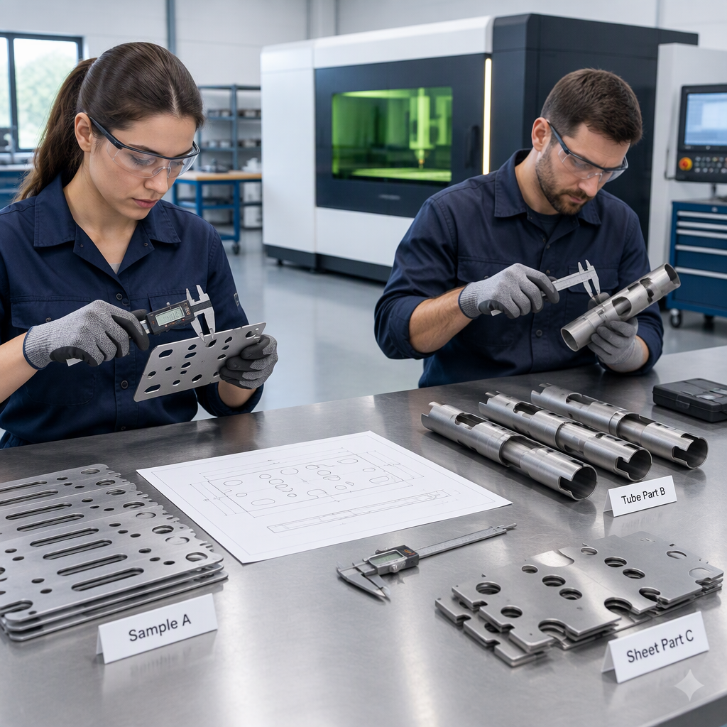
Define bed rigidity through production-part evidence
For a buyer, laser machine bed rigidity is best assessed as stable geometry under real cutting loads, motion and workholding, while remembering that the part result also includes axis errors, cutting parameters, measurement method and compensation choices.
A practical assessment starts with machine-tool error categories. NIST summarizes machine-tool errors as intra-axis, inter-axis and volumetric errors, and explains that measurement, modeling and compensation choices are selected around accuracy, complexity and cost in its machine-tool calibration publication.
Do not reduce the decision to a single cut edge. A part that looks acceptable may still hide direction-specific or volume-position errors, while a poor edge may come from focus, assist gas, nesting heat or fixturing rather than the bed.
For sheet metal and tube-processing factories, this keeps the discussion aligned with real selection inputs: material, thickness, workpiece size, application, production volume and automation requirements.
Know what production parts can and cannot prove
A production-part test can show whether the machine holds usable geometry on your parts, but it cannot by itself prove which machine structure or component caused the result.
What it can show
- Repeatability of holes, slots, diagonals and long edges across the machine work area.
- Whether geometric deviations appear in a consistent axis direction or position range.
- Whether quality changes after the machine is warm or after repeated processing.
What it cannot isolate
- It cannot separate intra-axis, inter-axis and volumetric error without a controlled measurement plan.
- It cannot remove thermal influence if ambient temperature, motors and processing heat are changing during the test.
- It cannot prove a supplier’s bed construction, machining process or rigidity value unless that data is supplied separately.
Use production parts to decide whether the delivered result fits your tolerance and throughput needs, then ask the supplier to explain the measurement method and machine settings behind that result.
Choose production parts and features that expose rigidity issues
Choose parts that represent your actual material, thickness, workpiece size and tolerance risks, not a supplier’s easiest demonstration geometry.
| Production feature | Why it helps the assessment | Buyer check |
|---|---|---|
| Long straight edges | They reveal directional geometry behavior over a longer travel distance. | Measure deviation at multiple positions, not only the end points. |
| Diagonal dimensions | They help expose combined axis and volumetric behavior. | Compare diagonals across repeated parts and bed positions. |
| Nested holes and slots | They show whether local features remain consistent during acceleration, direction change and contouring. | Measure hole-to-hole spacing and slot position, not only edge finish. |
| Repeated arrays or heat-intensive nests | They make thermal influence more visible than a single cold sample. | Record the sequence, elapsed time and machine temperature conditions where available. |
| Tube notches or sheet-and-tube families | They connect the test to the equipment category and workpiece type being purchased. | Use the same material, thickness and fixture approach expected in production. |
Separate rigidity from cutting-process variables
Before blaming bed rigidity, hold the cutting process, fixture, measurement method and environment as stable as possible because thermal deformation, processing heat and machine operation can affect volumetric error and part quality, as described in NIST’s thermal-deformation publication.
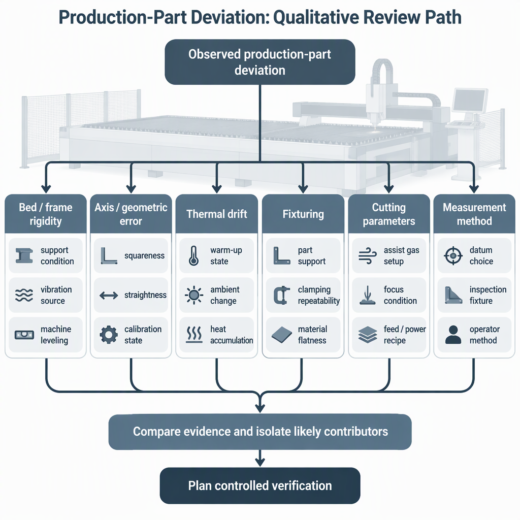
- Lock the assessment scope: material, thickness, workpiece size, application, expected production volume and automation needs.
- Use one approved drawing revision and define which dimensions are acceptance-critical.
- Keep program, nesting, nozzle condition, focus approach and assist-gas settings consistent during each comparison.
- Keep fixturing and loading method consistent, especially for tubes, long sheets and thin parts.
- Record ambient conditions, warm-up state and sequence timing so thermal drift is not mistaken for a static bed issue.
- Measure with the same gauge, fixture and operator method for each part set.
- Do not compare a cold first article against a warm repeated run without labeling the condition.
- Do not mix different material heats, thicknesses or protective films in one rigidity conclusion.
- Do not bypass guards or site laser-safety procedures during test cutting; follow the supplier’s current safety documentation and local requirements.
Include repeated cuts and thermal checks
One good sample is not enough because machine-tool deformation from motors, part processing and ambient temperature can dominate volumetric error and affect part quality.
- Cut an initial part set after the supplier’s normal preparation procedure.
- Cut repeated parts after the machine has run long enough to represent your production pattern.
- Place the same part or feature in different bed locations when the machine format allows it.
- Compare dimensions in the same measurement report format, including pass/fail rules agreed before the test.
- Look for drift by sequence: first part, middle parts and final parts may tell a different story than a single sample.
If a deviation grows as the machine warms, treat it as a thermal-and-geometric investigation, not as immediate proof that the bed alone is weak.
Build an RFQ and acceptance data checklist
Your RFQ should request the data needed to connect production-part results with geometry, process stability, thermal behavior and the supplier’s proposed machine configuration.
- List material grades, thickness ranges, part sizes, applications, production volume and automation requirements.
- Attach drawings with the dimensions that matter most for acceptance.
- Request the measurement method, gauge type and report format for sample parts.
- Ask how warm-up, ambient conditions and repeated cutting will be recorded.
- Ask which calibration, modeling or compensation approach the supplier uses for machine-tool errors.
- Request the supplier’s current safety documents and follow the applicable rules in your destination market before any test or acceptance run.
| If your priority is | Ask for | Why it matters |
|---|---|---|
| Flat sheet dimensional consistency | Repeated sheet-part reports across representative bed positions | Position-dependent results help reveal geometric behavior. |
| Tube fit-up quality | Tube sample reports using your real notch, hole and end-cut features | Workpiece type and application are core selection inputs. |
| Long production runs | Cold, warm and repeated-cut comparison records | Thermal deformation can affect volumetric error and part quality. |
| Supplier comparison | The same drawing, material, thickness and measurement plan for every bidder | Comparable measurement conditions reduce false conclusions. |
Apply the checklist to supplier discussions
Use the same checklist with DATO Laser or any other supplier: discuss your material, thickness, workpiece size, application, production volume and automation requirements first, then request model-specific sample and measurement data.
DATO Laser presents equipment categories including fiber laser cutting machines, tube laser cutting machines, sheet-and-tube laser cutting machines, laser welding, laser cleaning, marking, robotic welding and CNC press brakes. That supports a broad selection discussion, not a model-specific rigidity value or acceptance result.
Prepare a production-part acceptance pack before contacting suppliers: drawings, materials, thicknesses, tolerances, sample quantity, measurement method, expected production pattern and safety-document requirements.
Conclusion
The strongest buying decision comes from controlled production-part evidence, not from a visual inspection of the machine bed or a single attractive sample.
- Use real parts, but define which dimensions represent machine performance.
- Repeat the test under production-like thermal conditions.
- Tie every supplier discussion to material, thickness, workpiece size, application, production volume and automation needs.
Before RFQ or acceptance, give every supplier the same drawing package and require the same measurement logic. That is the fairest way to judge laser machine bed rigidity through production parts.
FAQ
These questions help buyers turn a laser machine bed rigidity discussion into a controlled production-part assessment.
Can one production part prove the bed is rigid?
No. One part can show a result under one condition, but machine-tool errors may be intra-axis, inter-axis or volumetric, so repeated and position-aware checks are more useful.
Is edge quality the same as bed rigidity?
No. Edge quality may be influenced by process settings and measurement conditions as well as machine geometry, so it should be evaluated alongside dimensions.
Why should I repeat the same cut after warm-up?
Repeated cutting helps reveal whether thermal deformation from motors, processing or ambient temperature is affecting volumetric error and part quality.
Which features should I measure first?
Start with the features that drive fit-up and scrap risk: long edges, diagonals, hole spacing, slots, tube notches and repeated arrays across the usable work area.
What should I ask a supplier before an acceptance test?
Ask for the drawing revision, measurement method, sample quantity, bed positions, machine condition, compensation approach and the pass/fail rules that will be used.
How should I discuss this with DATO Laser?
Discuss the application inputs first: material, thickness, workpiece size, production volume and automation requirements, then ask for model-specific sample data for the machine being quoted.
Do I need a separate safety review for test cutting?
Yes. Test cutting should follow the supplier’s current safety documentation and the rules that apply in your location; do not treat dimensional testing as a substitute for laser-safety review.
Related Blogs
-
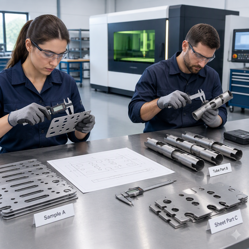 Learn how to assess laser machine bed rigidity with production parts, repeat cuts, process controls and RFQ data before supplier comparison.
-
 Common Robotic Laser Welding Defects: Causes and Troubleshooting StepsA robot can follow the same weld path thousands of times. That repeatability is valuable—but if a part shifts, a joint gap changes, or a process setting is unsuitable, the robot can also repeat the same defect.The most effective rBuyer's Guide
-
 Laser Welding Robot vs. Handheld Laser Welder: Which Fits Your Production?Should your factory invest in a laser welding robot or a handheld laser welder? Both use a laser to join metal, but they solve different production problems. A handheld system gives an operator direct control over the weldingBuyer's Guide
-
 How to Calculate Laser Welding Robot ROI for a Sheet Metal FactoryA laser welding robot may improve consistency and increase output, but those benefits do not automatically make it a profitable investment. For a sheet metal factory, the decision depends on the parts being welded, the volume of repeaBuyer's Guide


